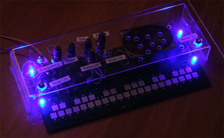
When I was young, my parents gave me a simple electronic piano, with some metal pads for the keys and a metal pen. It was a kit and it felt like magic with all theses electronic components, which produced sound when soldered correctly. Unfortunately I can't find it anymore, but building my own simple analog synthesizer sounds cool for a project for the 555 contest. This is the result:
My old synthesizer had a switchable vibrato, but I didn't manage to create a good one with a second 555 by changing the CV input of the first 555 with a LFO, it doesn't sound right. But instead my synth has some other nice features, like a filter and a volume envelope. This is the schematic, with a 555 timer chip:
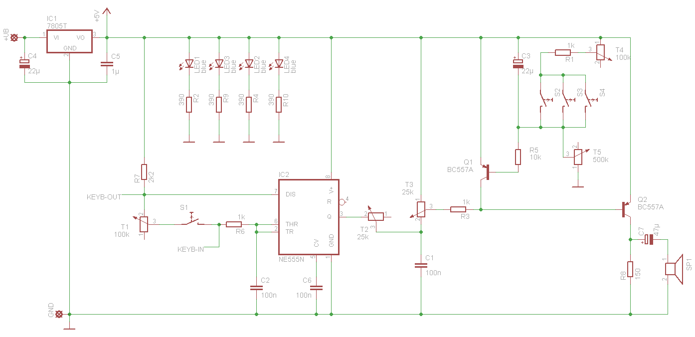
For a stable oscillating frequency, I've used a 7805 voltage regulator, which allows to supply it from 7 V to 20 V. When some sound is generated with the speaker, it needs about 60 mA. For higher input voltages you may need a heat sink for the 7805, but not e.g. for a 9 V battery.
The oscillator part is a 555 with a standard oscillator circuit. T2 and C1 is for the lowpass filter. T3 is for the volume and T4 and T5, with Q1 and the rest around Q1, is for the volume envelope with attack and release. Q2 is a standard class A amplifier for the speaker. S2, S3 and S4 are the "Note On" buttons in the video and the picture. Two of it are pushbuttons on the left and the right side and one is a toggle button, for constant signal generation.
The volume envelope works like this: when all "Note on" switches are off, C3 is charged by T5 and Q1 is conducting, which inhibits Q2. If you turn on one of the three switches, C3 is discharged and Q1 is not conducting any more, so Q2 is conducting and amplifying the sound. With T4 and T5 you can change the time constants how long it takes to charge and discharge C3.
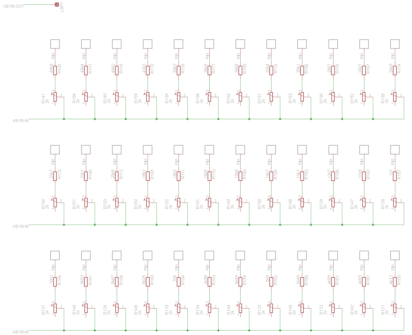
The keyboard:
And the PCB:
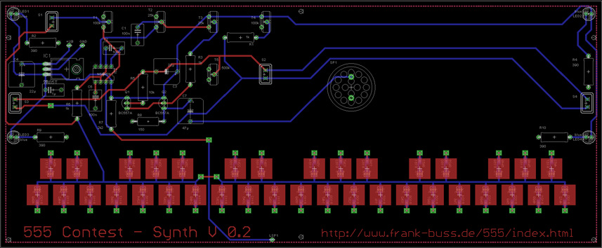
The Eagle files: eagle.zip. Compared to the version in the video below, this version 0.2 has the additional resistor R1 to avoid burning T4 and T5 and all values for the fixed resistors are entered. I've used resistors of the E96 series and 1 k below the calculated value, which was nearly the same as the measured value, so it is very linear, once you know the exact value of the factor for the capacitor. With the 2 k trimmers it can be adjusted very accurate.
Parts list:
| name | value | description |
|---|---|---|
| C1 | 100n | ceramic capacitor |
| C2 | 100n | ceramic capacitor |
| C3 | 22µ | elco |
| C4 | 22µ | elco |
| C5 | 1µ | ceramic capacitor |
| C6 | 100n | ceramic capacitor |
| C7 | 47µ | elco |
| IC1 | 7805T | voltage regulator |
| IC2 | NE555N | timer chip |
| LED1 | blue | 5 mm LED |
| LED2 | blue | 5 mm LED |
| LED3 | blue | 5 mm LED |
| LED4 | blue | 5 mm LED |
| Q1 | BC557A | PNP transistor |
| Q2 | BC557A | PNP transistor |
| R1 | 1k | resistor |
| R2 | 390 | resistor |
| R3 | 1k | resistor |
| R4 | 390 | resistor |
| R5 | 10k | resistor |
| R6 | 1k | resistor |
| R7 | 2k2 | resistor |
| R8 | 150 | resistor |
| R9 | 390 | resistor |
| R10 | 390 | resistor |
| R100 | 4k12 | resistor |
| R101 | 4k99 | resistor |
| R102 | 5k9 | resistor |
| R103 | 6k98 | resistor |
| R104 | 7k5 | resistor |
| R105 | 8k87 | resistor |
| R106 | 10k2 | resistor |
| R107 | 11k | resistor |
| R108 | 12k7 | resistor |
| R109 | 14k7 | resistor |
| R110 | 16k9 | resistor |
| R111 | 18k2 | resistor |
| R112 | 20k5 | resistor |
| R113 | 23k7 | resistor |
| R114 | 24k9 | resistor |
| R115 | 28k7 | resistor |
| R116 | 32k4 | resistor |
| R117 | 36k5 | resistor |
| R118 | 39k2 | resistor |
| R119 | 44k2 | resistor |
| R120 | 49k9 | resistor |
| R121-R156 | 2k | trimmer |
| R157 | 4k53 | resistor |
| R158 | 5k49 | resistor |
| R159 | 6k49 | resistor |
| R160 | 8k25 | resistor |
| R161 | 9k53 | resistor |
| R162 | 11k8 | resistor |
| R163 | 13k7 | resistor |
| R164 | 15k8 | resistor |
| R165 | 19k1 | resistor |
| R166 | 22k1 | resistor |
| R167 | 26k7 | resistor |
| R168 | 30k1 | resistor |
| R169 | 34k8 | resistor |
| R170 | 41k2 | resistor |
| R171 | 46k4 | resistor |
| S1 | SWITCH | switch |
| S2 | SWITCH | switch |
| S3 | SWITCH | button |
| S4 | SWITCH | button |
| SP1 | 8 ohm | speaker |
| T1 | 100k | potentiometer |
| T2 | 25k | potentiometer |
| T3 | 25k | potentiometer |
| T4 | 100k | potentiometer |
| T5 | 500k | potentiometer |
The small 2 k SMD trimmers are from Murata, PVZ2A202A01B00. You can buy it from Farnell. You'll need it, if you use the same layout, but otherwise you can use any type. Same for the other parts, they are not critical.
For my setup I've measured that the required resistance R per key is R=1/f/(1.45*C2)-R7 (with f=the frequency of the key, R7=1860 and C2=1e-7). Maybe your setup may vary, so some resistor kits are useful, like this one from Digikey with 0805 SMD resistors, or you could use two pots per note, one for coarse and one for fine tuning. You'll need at least a pot per note for fine tuning, otherwise it can sound very out of tune with 1% E96 resistor values.
I've tuned it for equal temperament. This means every pair of adjacent notes has a frequency ratio of 1.059463 (12th-root of 2, because of 12 semitones per octave). See this Excel table for the resistors and the frequency values of the notes: notes.xls
The synth in action and a time lapsed full documentation how I built it:
The volume envelope, low pass filter and amplifier are very simple and as a programmer I don't know much about analog electronics, so the values are most trial and error. I think there are many things to improve, e.g. I don't like that the volume pot changes the filter, too. But it was a fun project and you can use it for whatever you want. Please send me links of your construction or improvements, I'll add it to this page for reference, if someone wants to build it again.
