I've bought the C8051F34X Development Kit (which is available at Digikey for small money) because I want to play a bit with USB devices and testing the 8051 instruction set and architecture. The Blinky sample worked without problems with the IDE. Compiling larger programs is difficult, because the Keil compiler is an evaluation version, only, which limits the maximum program size. But there is SDCC support in the IDE. I tried it, but couldn't figure out how to define aliases for registers, so I installed a later version of the ASxxxx assembler, which was used by SDCC. This version doesn't work with the IDE, because the command line arguments are different and the required output file name and format is different (looks like the Silabs IDE can't use Intel Hex for the toolchain generated files). The editor in the IDE is not very good anyway, so I switched to my favorite editor Ultraedit and used a small build.cmd script for compiling the file:
C:\Programme\ASXV4PXX\ASXMAK\VC6\EXE\AS8051.EXE -slox blinky.asm
C:\Programme\ASXV4PXX\ASXMAK\VC6\EXE\ASLINK.EXE -i blinky blinky
xcopy /y C:\SiLabs\MCU\Examples\C8051F34x\Blinky\blinky.ihx "c:\Dokumente und Einstellungen\Frank\blinky.hex"
The IDE has a nice option "Download object file" in the Debug menu, where you can specify an Intel Hex file, which will be flashed to the device. This setup works, so finally I have mastered the usual development tool quirks.
The demo program samples the ADC, which is connected to the pin on the development board with a potentiometer. It sends the average of 16 values, sampled every millisecond, every 16 ms, with the P2.0 state (a button on the devboard) in bit 7. Received bytes from the serial port are written to P2 (only for P2.2 and P2.3, the other bits are overwritten with 1 to avoid problems with the open drain GPIOs). This is the source:
.include "c8051f340.inc"

GREEN_LED1 == P2.2                      ; green LED1
GREEN_LED2 == P2.3                      ; green LED2

.define TEMP      "R2"                  ; temporary register
.define ADC_COUNT "R3"                  ; current number of accumulated ADC samples
.define ADC_SUM_L "R4"                  ; accumulated samples value, low byte
.define ADC_SUM_H "R5"                  ; accumulated samples value, high byte

        .area   CODE (ABS)

        .org    0
reset:  ljmp    start                   ; reset vector

        .org    0x02B                   ; interrupt vector for timer2
        ajmp    timer2

        .org    0x100
start:  anl     PCA0MD, #0xff-0x40      ; clear watchdog enable bit
        mov     OSCICN, #0x83           ; set oscillator to full speed internal clock, 12 MHz

; setup 4x clock multiplier
        mov     CLKMUL, #0x00
        mov     CLKMUL, #0x80           ; enable clock multiplier
        clr     a                       ; wait a bit for initialization
        djnz    acc, .
        orl     CLKMUL, #0xc0           ; initialize clock multiplier
cinit:  mov     a, CLKMUL
        jnb     ACC.5, cinit            ; wait for stabilization
        mov     CLKSEL, #3              ; select full 48 MHz for system clock and USB clock

; setup ports
        orl     P2MDOUT, #0x0c          ; make LEDs pin output push-pull
        orl     P2MDIN, #0x0c           ; make LEDs pin input mode digital
        setb    GREEN_LED1              ; turn on LED1
        anl     P1MDIN, #0xff-0x02      ; set P1.1 as an analog input

; setup ADC
        mov     ADC0CN, #0x00           ; ADC0 disabled, normal tracking
        mov     REF0CN, #0x08           ; use VDD as AD reference
        mov     AMX0P, #0x04            ; ADC0 positive input = P2.5
        mov     AMX0N, #0x1F            ; ADC0 negative input = GND (single ended mode)
        mov     ADC0CF, #0xfc           ; set SAR clock to minimum and left-justify results
        setb    AD0EN                   ; enable ADC0
        mov     ADC_COUNT, #0x10        ; initialize counter for ADC accumulation

; setup timer2 for an interrupt every millisecond
        mov     TMR2CN, #0x00           ; stop timer2; clear TF2; use SYSCLK/12 as timebase for T2XCLK
        mov     TMR2RLH, #0xf0          ; init reload values
        mov     TMR2RLL, #0x60
        mov     TMR2H, #0xff            ; set to reload immediately
        mov     TMR2L, #0xff
        setb    ET2                     ; enable timer2 interrupts
        setb    TR2                     ; start timer2

; setup UART0
        orl     P0MDOUT, #0x10          ; enable UTX as push-pull output
        mov     XBR0, #0x01             ; enable UART on P0.4(TX) and P0.5(RX)
        mov     SCON0, #0x10            ; 8 bit, ignore stop bit, rx enabled, 9th bits are zeros, clear RI0 and TI0 bits
        mov     TH1, #0x30
        mov     TL1, #0x30
        orl     CKCON, #8               ; T1M = 1 (timer1 UART baud rate generator uses system clock)
        mov     TMOD, #0x20             ; timer 1 in 8-bit autoreload
        setb    TR1                     ; start timer1
        setb    TI0                     ; Indicate TX0 ready

        mov     XBR1, #0x40             ; enable Crossbar
        setb    EA                      ; enable global interrupts

        ajmp    .                       ; wait forever


; timer2 interrupt handler
timer2: clr     TF2H                    ; clear timer2 interrupt flag

        lcall   sample
        dec     ADC_COUNT
        mov     a, ADC_COUNT
        jnz     testA                   ; skip ADC output, until 16 values accumulated
        mov     ADC_COUNT, #0x10        ; reinitialize counter for ADC accumulation
        lcall   avg                     ; get average ADC value in accu
        anl     a, #0xfe                ; discard lsb
        rr      a
        jb      P2.0, notSet            ; test button
        orl     a, #0x80                ; set msb, if button is pressed
notSet: lcall   emit                    ; transfer to RS232

testA:  lcall   avail                   ; test if RS232 data is available
        jnb     ACC.0, iend
        mov     a, SBUF0                ; get byte
        orl     a, #0xf3                ; set 1 for all input pins
        mov     P2, a                   ; save in port2

iend:   reti                            ; return from interrupt


; sends a byte to RS232 and waits until transfered
emit:   mov     SBUF0, a                ; send byte
emit2:  mov     a, SCON0
        jnb     ACC.1, emit2            ; wait until transfered
        clr     SCON0+1                 ; clear transmit bit
        ret


; tests, if a byte is available from RS232
; return: accu=1, if available, 0 otherwise
avail:  mov     a, SCON0
        anl     a, #1
        clr     SCON0+0
        ret

; sample one ADC value and accumulate it in r5/r6
sample: setb    AD0BUSY                 ; start AD conversion
waitAD: mov     a, AD0BUSY              ; wait until AD conversion is finished
        jb      ACC.0, waitAD
        mov     a, ADC0H
        add     a, ADC_SUM_L
        mov     ADC_SUM_L, a
        jnc     s2
        inc     ADC_SUM_H
s2:     ret

; get the average of 16 accumulated ADC values from ADC_SUM and reinitialize it
; return: accu=average
avg:    mov     TEMP, #4
shift:  clr     C                       ; clear carry
        mov     a, ADC_SUM_H            ; shift ADC_COUNT_L/ADC_COUNT_H one bit right
        rrc     a
        mov     ADC_SUM_H, a
        mov     a, ADC_SUM_L
        rrc     a
        mov     ADC_SUM_L, a
        djnz    TEMP, shift             ; shift four times = divide by 16

        mov     a, ADC_SUM_L            ; return result in accu
        mov     ADC_SUM_L, #0           ; reinitialize ADC_SUM
        mov     ADC_SUM_H, #0
        ret
I like the instruction set, the bit-set and bit-clear operations are very handy. And many instructions of the C8051F34X chips are executed in one ow two clock cycles, which means you have up to 48 MIPS speed (but with some Silabs parts the system clock is limited to 25 MIPS). No external clock is required, the internal 12 MHz clock can be divided and multiplied up to 48 MHz, if the accuracy from 11.82 MHz to 12.18 MHz is sufficient.
Some time ago there was a full version of LabView in a German computer magazin DVD for personal use. I've seen some expensive PCI cards for integration with LabView, with ADC, GPIOs etc., but for many tasks the multiplexed ADCs and many GPIOs of one Silabs chip, wired with RS232 to the PC, is all you need to control and measure some external hardware, so this was a good test for me to try out LabView, because the graphical, schematic-like programming environment looks very user friendly and easier for electronic engineers than writing some text programs. And after reading some tutorials, finally I managed to create my first Virtual Instrument. Once you have learned the basics, it is very easy to create your own instruments. To do all the minor format conversions, numerical constants etc. with symbols needs getting used to, but the same is true for writing programs with a text editor. I don't know how it scales for bigger projects (but you can encapsulate functionalities inside user defined symbols, which should help), but this small project looks very nice and clear, and it is fun to work with.
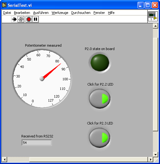
This is the GUI of the virtual instrument:
The pointer of the round instrument is updated very fast when tuning the potentiometer and there is nearly no CPU usage.
The flow diagram for this instrument:
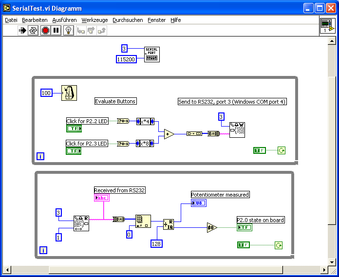
You can download the instrument. Maybe I'll buy the commercial version and use it more often instead of writing text programs. For virtual instruments it is more natural to just draw it instead of writing lots of text for implementing it.
