You can buy it at mirifica
This board uses the PCA9555 IO expander for 16 individually as input or output programmable signals. The lower 3 bits of the I2C address can be changed by connecting A0 to A2 to Vdd, for up to 8 boards on one I2C bus. You can power the Vdd with 5 V or 3.3 V. Or you can use the 3.3 V power supply and connect the 3.3 V output to Vdd. The 3.3 V regulator provides up to 250 mA for the IO expander and external components together. The voltage regulator has an integrated short circuit and overheat protection. You can use up to 16 V at the +5V input pin for the regulator, if the power dissipation is not too high.
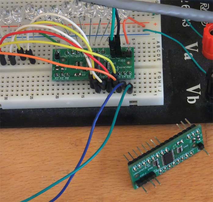
For each of the connections GND, SCL, SDA, Vdd, 3V3 and +5V there are two pins. The idea is to use the outer header row for the connection to a breadboard and the inner header row mounting on top of the IO expander board to connect with ready-made wires with a female connector at the end to other boards, see the picture at the end of this page for an example how to mount the headers. If you have an Arduino, then you can use wires with a female connector on the side of the IO expander board, and a male connector on the side for the Arduino. If you have a Raspberry Pi with a populated pin header, then you can use a female/female wire. Or you could just solder wires in the inner holes.
All 16 IO connections are protected with a 680 ohm serial resistor. This means you can connect standard low power LEDs without an additional serial resistor. You can even short-circuit all outputs to GND without damaging the board, which is good for educational usage.
Example code in C how to use it from Linux, as seen in the video: linux-i2c-test.c
Same example in Python: i2c-test.py
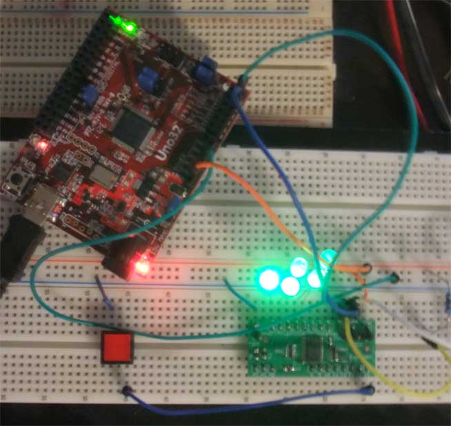
Test with Uno32: arduino.txt
Raspberry Pi is a trademark of the Raspberry Pi Foundation
