This is the beginning of my evaluation of the PCI18F2550. First I got the latest MPLAB IDE, version 8.36, because my version was a bit outdated. The setup install the IDE and the HI-TECH C compiler and the Microchip PIC32 C-Compiler, but seems like they don't work for the PIC18 series. I have a commercial version of C18, a good compiler, but to learn the basics of the PIC18 series and the new instructions compared to the PIC16 series I'm used to, I created a project with the Microchip MPASM toolsuite, which is free and used for assembler programs.
First I went the easy way and copied a LED blinking program from some webpage. When trying to compile it, the compiler ask for "Absolute" or "Reloctable" code. Ok, I didn't read the manual, so I choosed "Relocatable". There was a line like "delay res 1" in the code and the compiler said "No memory has been reserved by this instruction". After changing to "Absolute", the compiler said "RES directive cannot reserve odd number of bytes in PIC18 absolute mode".
Ok, time to read the manual. The reason for the problems: "Relocatable" means that it behaves like other bigger compiliers: it creates obj files, to allow splitting a project in many modules, which are later linked by the linker to the final program. Like in other compilers, you can specify sections like "data", where you can define variables and "code" for code. In data sections you can reserve memory from the SRAM with "res". The final address is later assigned by the linke, because multiple modules can reserve memory with "res" and can be assembled differently for each project. You can find details about this in MPLAD IDE, see Help->Topics and then MPASM etc. For the rest of this article I'm using the "Absolute" mode.
In "Absolute" mode usually only one source is compiled and the final program is created from it. Seems like the "res" command tries to reserve memory in the flash, which is not possible for one byte, because instructions are 16 bit long and must always start at even addresses, which was the reason for the error message. In order to define variables, you have to define constants (at least I think there is no other way in absolute mode), which points to memory addresses in SRAM (see Harvard architecture in the datasheet for details). You can do this with "equ", but if you want to define multiple variables, you better use cblock/endc, because then it is easier to add or remove variables without the need to manually adjust all addresses.
My first goal was to create a 1 ms interrupt and of course, a blinking LED. In less expensive PICs it is not possible to generate interrupts on arbitrary timer values, only on overflow. This means you'll get some jitter, if you reload the timer registers within the interrupt for timing the next interrupt. My hope was, that this is possible without manual reloading with the PIC18.
First I configured the device. The easiest way is to open the header file for your CPU, search for the config comments and read the datasheet for each config option block, then copy one to your source. Doing it this way there is no suprise, if you e.g. forget to disable the watchdog. For the clock input I used a 4 MHz crystal oscillator and the PIC is configured to use the internal PLL for creating 96 MHz and then dividing it by 2 for the 48 MHz CPU and USB clock. In the datasheet this frequency is called "Fosc". Many functions can be driven with this clock. Some additional PIC basics: One instruction cycle needs four Fosc cycles. Most instructions need one instruction cycle, so this means you'll get a 12 MIPS microcontroller for some bucks (note: you can't use 48 MHz with 3V supply voltage and only the LF version works with 3V for 16 MHz, see datasheet electrical characteristics). An additional nice feature for some applications: There is a hardware mutliplier instruction, which needs 1 instruction cycle for multipliying two 8 bit values and creating a 16 bit result (for unsigned numbers).
The setup for my interrupt requirements are a bit complicated, but possible. I feed the 48 MHz clock to timer 3 (with a divide by 8 pre-scaler). Then I use the Capture/Compare/PWM modul number 2 for raising an interrupt and resetting the timer 3, if a user defined timer value is reached. Now it is possible to create interrupts with 1 ms speed, or 10 ms, or even 10 µs. I didn't found anything like this for the other timers, with a 16 bit compare value. Sometimes they can only generate overflow interrupts, sometimes they are not 16 bit wide. The architecture is not very orthogonal, but sometimes a bit weird.
In the interrupt function there is a counter running to 500 and then inverting a port bit for a 1 Hz blinking LED. In the main function there is an echo test, which reads the serial port and outputs it to the serial port.
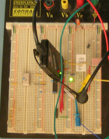
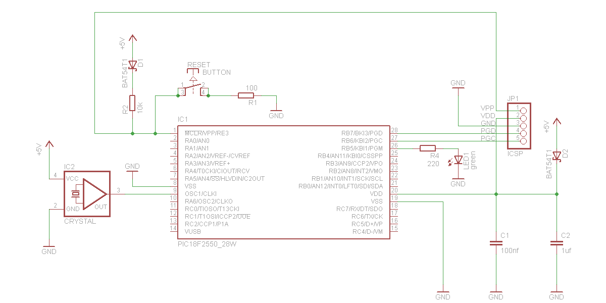
The schematic is simple and you can build it without problems on a breadboard:
You can use a level converter for RC6 and RC7 (e.g. MAX232) for connecting it to an RS232 interface to your PC. With a terminal program you can enter text, which is echoed by the PIC.
JP1 is for the programmer. I'm using the PICkit 2, which is not too expensive and works very nice. But there are some cheaper do-it-yourself programmers, too.
Because of the diode you can leave the programmer connected all the time to the board, even if it is powered by an external power supply. But after flashing you have to click "Release from Reset" in the MPLAB-IDE. Important: Activate the programmer first, then plug it into your board, because seems like the programmer pulls VDD to low, if deactivated.
If you don't use the LVP programming method, you could even use the VPP pin as the RE3 port, but for prototyping I've configured it as the reset input. The PGM pin can be used, too, which is used for the 1 Hz blinking LED. When LVP is configured, you can't use this pin as a user pin. But you'll need a higher programming voltage on VPP. You can find details about this in the datasheet and the application notes from Microchip.
This is the code I described, which works with the schematic:
#include <p18F2550.inc>

; use decimal numbers as default, if specified without prefix, like "0x"
    radix dec

; move literal to file register W = literal
movlf       macro x, y
                movlw x
                movwf y
            endm

            CONFIG PLLDIV = 1           ; No prescale (4 MHz oscillator input drives PLL directly)
            CONFIG CPUDIV = OSC1_PLL2   ; [OSC1/OSC2 Src: /1][96 MHz PLL Src: /2]
            CONFIG USBDIV = 1           ; USB clock source comes directly from the primary oscillator block with no postscale
            CONFIG FOSC = ECPLLIO_EC    ; External clock, PLL enabled, port function on RA6, EC used by USB
            CONFIG FCMEN = OFF          ; Fail-Safe Clock Monitor disabled
            CONFIG IESO = OFF           ; Oscillator Switchover mode disabled
            CONFIG PWRT = ON            ; Power-up Timer enabled
            CONFIG BOR = ON             ; Brown-out Reset enabled in hardware only (SBOREN is disabled)
            CONFIG BORV = 2             ; Brown-out Voltage 2.8 V
            CONFIG VREGEN = ON          ; USB voltage regulator enabled
            CONFIG WDT = OFF            ; Watchdog Timer Disabled - SW Controlled
            CONFIG MCLRE = ON           ; MCLR pin enabled; RE3 input pin disabled
            CONFIG LPT1OSC = OFF        ; Timer1 configured for higher power operation
            CONFIG PBADEN = OFF         ; PORTB<4:0> pins are configured as digital I/O on Reset
            CONFIG STVREN = ON          ; Stack full/underflow will cause Reset
            CONFIG LVP = OFF            ; Single-Supply ICSP disabled
            CONFIG XINST = OFF          ; Instruction set extension and Indexed Addressing mode disabled
            CONFIG DEBUG = OFF          ; Background debugger disabled, RB6 and RB7 configured as general purpose I/O pins

; fosc is 48 MHz. Timer source is fosc/4. Prescaler /8 gives 1.5 MHz.
; CCP2 compares with 1500, which results in 1 ms interrupts
; Use e.g. 150 for 0.1 ms interrupts.
tickPeriod  equ 1500

; blinker period: the LED is inverted each 500 ticks, so it blinks with 1 Hz
blinker     equ 500

; define variables, starting from SRAM address 0
            cblock 0
                counter:2               ; 16 bit for counter
            endc

; reset vector
            org 0
            goto start

; high priority interrupt
            org 0x08
            goto interrupt

; low priority interrupt not defined, restart
            org 0x18
            goto start

start:
; init variables
            clrf counter
            clrf counter+1

; port initialization
            clrf PORTB                  ; set all pins on PORTB to 0
            clrf TRISB                  ; set all pins on PORTB to output
            movlf b'11000000', TRISC    ; RX/TX setup

; serial port initialization
            movlf 25, SPBRG             ; 115,200 baud at 48 MHz (effective baudrate: 115,384.6 baud, 0.16 % error)
            movlf b'10010000', RCSTA    ; enable receiver
            movlf b'00100100', TXSTA    ; enable transmitter and set high speed baud rate select bit

; timer and interrupt initialization
            movlf high tickPeriod, CCPR2H
            movlf low tickPeriod, CCPR2L
            movlf b'00111001', T3CON    ; prescaler 8, timer 3 source for CCP2, timer 1 source for CCP1
            movlf b'00000001', PIE2
            clrf CCP2CON
            movlf b'00001011', CCP2CON  ; reset timer and start A/D conversion on CCP2 match, if enabled
            bcf PIR2, CCP2IF
            movlf b'11000000', INTCON   ; enable global interrupt and peripheral interrupts for CCP2

; echo serial port input
mainLoop:   btfsc PIR1, RCIF            ; skip next instruction, if no byte was received
            movff RCREG, TXREG          ; move received byte to transmit register
            goto mainLoop

interrupt:  incfsz counter
            goto testBlink
            incf counter+1
testBlink:  movlw high blinker
            cpfseq counter+1
            goto iend
            movlw low blinker
            cpfseq counter
            goto iend

; counter reached blink period, clear counter and toggle LED
            clrf counter
            clrf counter+1
            btg PORTB, 5, 0

; clear interrupt flag and return from interrupt
iend:
            bcf PIR2, CCP2IF
            retfie

            end
Some parts of the code are already prepared for the USB test, which I want to implement later. This is a photo of the test setup: