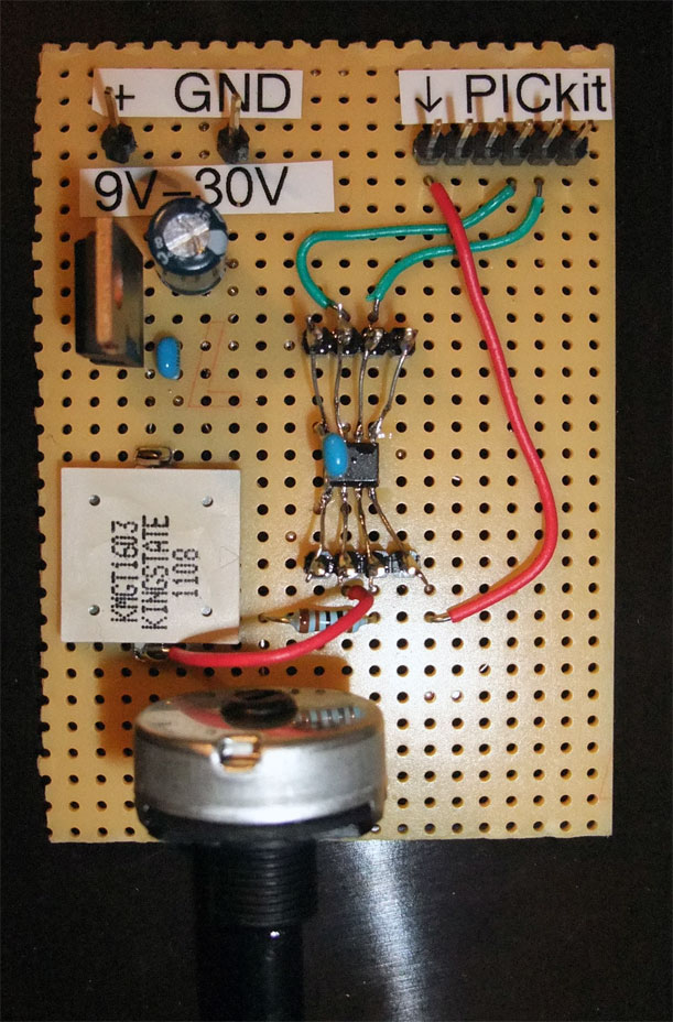
Creates a square wave from 50 Hz to 4 KHz on GP5, when the voltage at GP4 changes from 0.5 V to 2.5 V. The schematic is just the PIC12F675 and a 100 nF decoupling capacitor. My test setup includes a 7805 voltage regulator and a 1 k potentiometer for simulating the voltage input. Another 1 k resistor protects the potentiometer, if I switch the input to output. A piezo speaker generates some sound. And finally some headers for supply and the PICkit2 programming adapter:
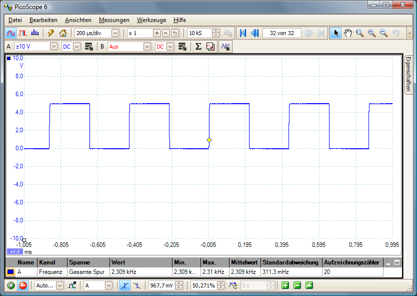
Example output for 1.6 V at GP4:
The firmware is written in C with the free HI-TECH PICC-Lite compiler. It is even possible to use floating point variables and operations, which makes the program very easy, see the source. The full MPLAB project: vco.zip
Known problems: The internal oscillator is calibrated to +/- 1% and there is no capture and compare timer register, which results in some jitter and less accuracy, especially for higher frequencies. The measured frequency range is between 49 Hz and 4.1 kHz.
