This clock generator provides four outputs:
The rawClockOut is a special output: if the divider output is selected, it is the same signal as clockOut. But you can specify the data-in signals to be latched at the (divided) edge of the out1 signal. In this case the out1 and out2 signals are not driven by the divider, but by the latched data. The clockOut signal is derived from this new output. For triggering external hardware, the latch clock is fed to the rawClockOut in this case.
An optional prescaler divides the clockIn signal: 2, 4, 6, 8...256.
The timing values can be set with a simple SPI-like serial interface. While setting new values, the outputs can be disabled (set to 0).
Example applications:
With some project setting adjustments (e.g. optimize for area, not for speed), the design below fits in a Xilinx XC9572XL CPLD, with fMax = 35.971 MHz. Resource usage:
| Macrocells | 67/72 (94%) |
|---|---|
| Pterms | 201/360 (56%) |
| Registers | 53/72 (74%) |
| Pins | 10/72 (14%) |
| Function Block Inputs | 93/216 (44%) |
library ieee;
use ieee.std_logic_1164.all;
use ieee.numeric_std.all;
use ieee.std_logic_unsigned.all;

entity main is
	port(
		clockIn: in std_logic;
		data: in std_logic_vector(1 downto 0);

		controlData: in std_logic;
		controlClock: in std_logic;

		outEnable: in std_logic;

		rawClockOut: out std_logic;
		out1: out std_logic;
		out2: out std_logic;
		clockOut: out std_logic
	);
end main;

architecture rtl of main is
	-- regs memory
	signal regs: unsigned(29 downto 0) := (others => '0');

	-- regs aliases
	signal div1LowCountReg: unsigned(4 downto 0);
	signal div1HighEndReg: unsigned(4 downto 0);
	signal div2HighStartReg: unsigned(4 downto 0);
	signal div2HighCountReg: unsigned(4 downto 0);
	signal prescaleCounterReg: unsigned(6 downto 0);
	signal delayDiv2Reg: std_logic;
	signal useDataInputReg: std_logic;
	signal prescaleBypassReg: std_logic;

	signal counter1: natural range 0 to 31 := 0;
	signal counter2: natural range 0 to 31 := 0;
	signal div1: std_logic := '0';
	signal div2: std_logic := '0';
	signal div2Delayed: std_logic := '0';
	signal latchedData: std_logic_vector(1 downto 0);
	signal clock: std_logic := '0';
	signal prescaledClock: std_logic := '0';
	signal prescaleCounter: natural range 0 to 127 := 0;

begin

	-- set the control register bits
	controlProcess: process(controlClock)
	begin
		if rising_edge(controlClock) then
			regs <= controlData & regs(29 downto 1);
		end if;
	end process;
	div1LowCountReg <= regs(4 downto 0);
	div1HighEndReg <= regs(9 downto 5);
	div2HighStartReg <= regs(14 downto 10);
	div2HighCountReg <= regs(19 downto 15);
	delayDiv2Reg <= regs(20);
	useDataInputReg <= regs(21);
	prescaleCounterReg <= regs(28 downto 22);
	prescaleBypassReg <= regs(29);

	-- clock prescaler
	prescalerProcess: process(clockIn)
	begin
		if rising_edge(clockIn) then
			if prescaleCounter = prescaleCounterReg then
				prescaleCounter <= 0;
				prescaledClock <= not prescaledClock;
			else
				prescaleCounter <= prescaleCounter + 1;
			end if;
		end if;
	end process;

	-- select prescaled clock or full speed
	clock <= clockIn when prescaleBypassReg = '1' else prescaledClock;

	-- generate div1 and div2
	divideProcess: process(clock)
	begin
		if rising_edge(clock) then
			-- generate div1 signal
			div1 <= '0';
			if counter1 < div1LowCountReg then
				counter1 <= counter1 + 1;
			else
				div1 <= '1';
				if counter1 < div1HighEndReg then
					counter1 <= counter1 + 1;
				else
					counter1 <= 0;
					latchedData <= data;
				end if;
			end if;

			-- div2 signal starts at a fixed time offset from the start of div1 signal
			if counter1 = div2HighStartReg then
				div2 <= '1';
				counter2 <= 0;
			else
				if counter2 < div2HighCountReg then
					counter2 <= counter2 + 1;
				else
					div2 <= '0';
				end if;
			end if;

		end if;
	end process;

	-- half clock cycle delay for div2
	delay: process(clock)
	begin
		if falling_edge(clock) then
			div2Delayed <= div2;
		end if;
	end process;

	-- generate the output signals
	outputGenerator: process(clock, outEnable, delayDiv2Reg, useDataInputReg, latchedData, div1, div2, div2Delayed)
		variable div2Selected: std_logic;
	begin
		-- select synchronous div1/div2 or delayed div2
		if delayDiv2Reg = '1' then
			div2Selected := div2Delayed;
		else
			div2Selected := div2;
		end if;

		-- if output is not enabled, all outputs are set to 0
		if outEnable = '1' then
			if useDataInputReg = '1' then
				-- overwrite output with latched data
				out1 <= latchedData(0);
				out2 <= latchedData(1);
				clockOut <= latchedData(0) xor latchedData(1);

				-- rawClock output is divided clock signal in overwrite mode
				rawClockOut <= div1;
			else
				-- use the divided signals
				out1 <= div1;
				out2 <= div2Selected;
				clockOut <= div1 xor div2Selected;
				rawClockOut <= div1 xor div2Selected;
			end if;
		else
			out1 <= '0';
			out2 <= '0';
			clockOut <= '0';
			rawClockOut <= '0';
		end if;
	end process;

end architecture rtl;
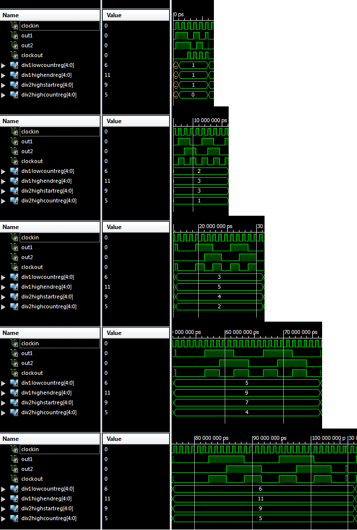
The testbench below demonstrates how to configure it to divide clockIn by 1, 2, 3, 4 and 5. Timing diagram:
library ieee;
use ieee.std_logic_1164.all;
use ieee.numeric_std.all;
use ieee.std_logic_unsigned.all;

entity test is
end test;

architecture test of test is

	component main
		port(
		clockIn : in std_logic;
		data :  in std_logic_vector(1 downto 0);
		controlData : in std_logic;
		controlClock : in std_logic;
		outEnable : in std_logic;
		rawClockOut : out std_logic;
		out1 : out std_logic;
		out2 : out std_logic;
		clockOut : out std_logic
		);
	end component;


	--Inputs
	signal clockIn : std_logic := '0';
	signal data : std_logic_vector(1 downto 0) := (others => '0');
	signal controlData : std_logic := '0';
	signal controlClock : std_logic := '0';
	signal outEnable : std_logic := '1';

	--Outputs
	signal rawClockOut : std_logic;
	signal out1 : std_logic;
	signal out2 : std_logic;
	signal clockOut : std_logic;

	-- Clock period definitions
	constant clockPeriod : time := 1us;

	-- controls values
	signal div1LowCountReg: std_logic_vector(4 downto 0);
	signal div1HighEndReg: std_logic_vector(4 downto 0);
	signal div2HighStartReg: std_logic_vector(4 downto 0);
	signal div2HighCountReg: std_logic_vector(4 downto 0);
	signal delayDiv2Reg: std_logic;
	signal useDataInputReg: std_logic;
	signal prescaleCounterReg: std_logic_vector(6 downto 0);
	signal prescaleBypassReg: std_logic;

	begin

	-- Instantiate the Unit Under Test (UUT)
	uut: main port map (
		clockIn => clockIn,
		data => data,
		controlData => controlData,
		controlClock => controlClock,
		outEnable => outEnable,
		rawClockOut => rawClockOut,
		out1 => out1,
		out2 => out2,
		clockOut => clockOut
	);

	-- Clock process definitions
	clockProcess: process
	begin
		clockIn <= '0';
		wait for clockPeriod/2;
		clockIn <= '1';
		wait for clockPeriod/2;
	end process;

	-- Stimulus process
	stim_proc: process
		procedure sendControl is
			variable word: std_logic_vector(29 downto 0);
		begin
			wait for 1ns;
			word := prescaleBypassReg & prescaleCounterReg & useDataInputReg & delayDiv2Reg & div2HighCountReg & div2HighStartReg & div1HighEndReg & div1LowCountReg;
			for i in 0 to 29 loop
				controlData <= word(i);
				controlClock <= '0';
				wait for 1ns;
				controlClock <= '1';
				wait for 1ns;
			end loop;
			controlClock <= '0';
		end;
	begin
		wait for clockPeriod;

		-- test divide by 1
		div1LowCountReg <= std_logic_vector(to_unsigned(1, 5));
		div1HighEndReg <= std_logic_vector(to_unsigned(1, 5));
		div2HighStartReg <= std_logic_vector(to_unsigned(1, 5));
		div2HighCountReg <= std_logic_vector(to_unsigned(0, 5));
		delayDiv2Reg <= '1';
		useDataInputReg <= '0';
		prescaleBypassReg <= '1';
		sendControl;
		wait for clockPeriod*10/2;

		-- test divide by 2
		div1LowCountReg <= std_logic_vector(to_unsigned(2, 5));
		div1HighEndReg <= std_logic_vector(to_unsigned(3, 5));
		div2HighStartReg <= std_logic_vector(to_unsigned(3, 5));
		div2HighCountReg <= std_logic_vector(to_unsigned(1, 5));
		delayDiv2Reg <= '0';
		useDataInputReg <= '0';
		prescaleBypassReg <= '1';
		sendControl;
		wait for clockPeriod*20/2;

		-- test divide by 3
		div1LowCountReg <= std_logic_vector(to_unsigned(3, 5));
		div1HighEndReg <= std_logic_vector(to_unsigned(5, 5));
		div2HighStartReg <= std_logic_vector(to_unsigned(4, 5));
		div2HighCountReg <= std_logic_vector(to_unsigned(2, 5));
		delayDiv2Reg <= '1';
		useDataInputReg <= '0';
		prescaleBypassReg <= '1';
		sendControl;
		wait for clockPeriod*30/2;

		-- test divide by 4
		div1LowCountReg <= std_logic_vector(to_unsigned(4, 5));
		div1HighEndReg <= std_logic_vector(to_unsigned(7, 5));
		div2HighStartReg <= std_logic_vector(to_unsigned(6, 5));
		div2HighCountReg <= std_logic_vector(to_unsigned(3, 5));
		delayDiv2Reg <= '0';
		useDataInputReg <= '0';
		prescaleBypassReg <= '1';
		sendControl;
		wait for clockPeriod*40/2;

		-- test divide by 5
		div1LowCountReg <= std_logic_vector(to_unsigned(5, 5));
		div1HighEndReg <= std_logic_vector(to_unsigned(9, 5));
		div2HighStartReg <= std_logic_vector(to_unsigned(7, 5));
		div2HighCountReg <= std_logic_vector(to_unsigned(4, 5));
		delayDiv2Reg <= '1';
		useDataInputReg <= '0';
		prescaleBypassReg <= '1';
		sendControl;
		wait for clockPeriod*50/2;

		-- test divide by 6
		div1LowCountReg <= std_logic_vector(to_unsigned(6, 5));
		div1HighEndReg <= std_logic_vector(to_unsigned(11, 5));
		div2HighStartReg <= std_logic_vector(to_unsigned(9, 5));
		div2HighCountReg <= std_logic_vector(to_unsigned(5, 5));
		delayDiv2Reg <= '0';
		useDataInputReg <= '0';
		prescaleBypassReg <= '1';
		sendControl;
		wait for clockPeriod*60/2;

		assert false report "No failure, simulation was successful." severity failure;

	end process;

end;
